Introduction
In the first post of this series, I presented an overview of the NES and its subsystems. A key component is the CPU, which is a version of the MOS Technology 6502 CPU. To write games for the NES, it is necessary to understand how this CPU functions and how to program it using assembly. This post covers the basics that you will need.
The main reference used in this post is the original MOS MCS6500 microcomputer family programming manual. It is a dense read but it does include a lot of useful advice and many worked examples. You can ignore any information about the 6502's binary coded decimal mode as it is not supported by the NES's CPU.
If you have not done so already, I recommend that you read the first post in this series before this one.
Basic assembly language syntax
This section is a very basic introduction to assembly language syntax. The exact syntax will depend on your choice of compiler toolchain. The information here is correct for the toolchain that I will cover later in this series.
Literals
Binary literals
Binary literal values are prefixed by a percent sign, for example %00000100.
A bit is set if it has the value 1 and is clear or not set if it has the value 0. If the binary value has 8 bits then it represents one byte. Occasionally you will see two-byte values written in binary, for example %0000000011111111.
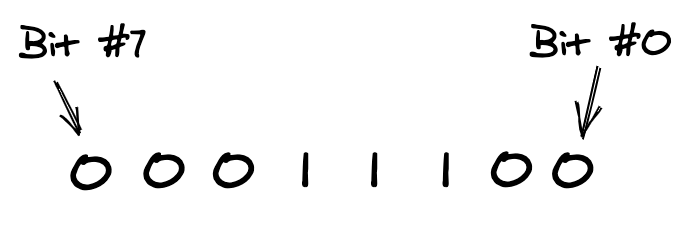
The bits of a byte are numbered from 0 to 7. Bit #0 is the least significant (rightmost) bit and bit #7 is the most significant (leftmost) bit:
Hexadecimal literals
Hexadecimal, or hex, literal values are prefixed by a dollar sign, for example $0F.
Each digit in a hex literal represents a nibble. A byte consists of two nibbles, so a single byte is written as two hex digits. A two-byte value is written as four hex digits. Thus $3F represents a byte value and $C008 represents a two-byte value.
The first byte of a two-byte value is the most significant byte (MSB). The second byte is the least significant byte (LSB). So given the hex value $C008, the MSB is $C0 and the LSB is $08.
Decimal literals
A literal value is a regular decimal value if it has no dollar sign or percent sign prefix.
Comments
Comments in assembly are prefixed by a semicolon. The content of the comment is everything after the semicolon to the end of the current line.
; This whole line is a comment

LDA #$04 ; This comment comes after an instruction
Opcodes
A program instruction represents a particular operation for the CPU to perform. It may or may not include an operand. The instruction operation code (opcode) used in the instruction identifies the operation. The opcode is a byte value in the range 0 to 255 inclusive. The 6502 supports 151 opcodes and they are grouped into 56 operations. Each opcode in a group performs the same basic operation, such as adding two numbers together. They differ by the addressing mode used to specify the data to operate on. (I cover addressing modes later in this post.)
For each instruction in your program, the assembler needs to determine the opcode to use. You state the basic operation by the particular three-letter mnemonic that you use. This mnemonic is not case sensitive.
SEI       ; The mnemonic is SEI.
sei       ; You can write the mnemonic in lowercase.
LDA $0211 ; This instruction has the mnemonic LDA
          ; and it is followed by an operand.
You state the addressing mode by either omitting the operand or by the syntax you use to define it. The assembler uses the mnemonic and the addressing mode to work out which opcode to output. As an example, let us consider the operation 'Add memory to Accumulator with Carry'. It has the mnemonic ADC. All the following instructions use that mnemonic and an operand value of $04:
ADC #$04     ; The opcode is $69.
ADC $04, X   ; The opcode is $61.
ADC ($04), Y ; The opcode is $71.
What differs is the syntax used to define the operand. The particular syntax you use tells the assembler which addressing mode to use. This allows it to choose which one of the ADC opcodes to output.
The assembler outputs the opcode first and the operand second, if there is one. The operand is one or two bytes in size so every machine instruction is either one, two, or three bytes in size.
The 6502 is little endian so any addresses in the program get encoded LSB first and MSB second. If an operation has an operand of the address $1234 then the assembler will encode that address as $3412. (Here $12 is the MSB and $34 is the LSB.)
Labels
You can use a label to associate a name with a particular location in the program code. The assembler replaces any uses of a label with the address of that location or the relative offset to it. (The exact replacement value depends on the addressing mode used.) Using labels makes your code more readable and avoids hardcoded program addresses.
You declare each label as a case-insensitive identifier followed by a colon. The following code declares the label this_is_a_label:
this_is_a_label:
  LDA #$00
You can now use this label as an operand. The following instruction jumps the program to wherever you declared the given label:
JMP this_is_a_label
You can also declare a label on the same line as an instruction:
some_label: LDA #$00
Some assemblers support other types of label. A cheap local label allows you to reuse common labels. For example, you can reuse the label 'loop'. This means that you do not need to create a unique label every time you loop over a series of instructions:
@loop:      ; A cheap local label
  JMP @loop ; Example usage of the cheap local label
Unnamed labels fulfil a similar role but they make the program code harder to understand:
:           ; An unnamed label
  JMP :-    ; This jumps backwards to the last unnamed label
Constants
Programming in assembly can involve a lot of magic values. These include the addresses of bytes in the CPU's address space that control the PPU. Assemblers usually support declaring numeric constants. These allow you to reference values by name and so improve the readability of your code:
PPUCTRL            = $2000     ; An address constant.
BACKGROUND_ENABLED = %00001000 ; A bitmask constant.
You can use constants as instruction operands:
STA PPUCTRL
It is common to use uppercase for the names of constants.
Embedded bytes
Sometimes you will need to embed data in your program. For example, you might need to embed colour palette data. An assembler will include a means for doing so. The following assembly embeds some data into the program code:
.byte $02,$30,$20,$20 ; Embeds these four one-byte values.
.word $1234           ; Embeds this single two-byte value.
.addr some_label      ; Embeds the address associated with the label.
In this assembler dialect, .byte, .word and .addr are instructions for the assembler. We term these assembler instructions control commands.
Binary number theory
This section introduces concepts about binary numbers. This information will make later sections easier to understand.
Unsigned and signed binary values
A byte consists of 8 bits, from bit #0, the least significant bit, to bit #7, the most significant bit. One interpretation of these bits is that they represent an unsigned value in the range $00 to $FF (0 to 255 in decimal):
%00000000 ; Smallest 8-bit unsigned value (0 in decimal).
%11111111 ; Largest 8-bit unsigned value (255 in decimal).
An alternative interpretation is that they represent a signed value. In that case, bit #7 indicates if the value is negative — when it is set — or positive — when it is not set. Bits #0 to #6 give the size of this positive or negative value. This corresponds to the two's complement representation for signed binary values. The following values illustrate this representation:
%00000000 ; Positive 8-bit signed value with smallest magnitude (0 in decimal).
%01111111 ; Positive 8-bit signed value with largest magnitude (+127 in decimal).

%11111111 ; Negative 8-bit signed value with smallest magnitude (-1 in decimal).
%10000000 ; Negative 8-bit signed value with largest magnitude (-128 in decimal).
Multi-byte binary values
We can represent larger unsigned and signed values by increasing the number of bits. For example, a 16-bit (two byte) value can represent an unsigned value in the range 0 to 65,535:
%0000000000000000 ; Smallest 16-bit unsigned value (0 in decimal).
%1111111111111111 ; Largest 16-bit unsigned value (65,535 in decimal).
For signed multi-byte values, regardless of the total bit count, it is always bit #7 of the MSB that is the sign bit. The following signed 16-bit values illustrate this:
%0000000000000000 ; Positive signed value with smallest magnitude (0 in decimal).
%0111111111111111 ; Positive signed value with largest magnitude (+32,767 in decimal).

%1111111111111111 ; Negative signed value with smallest magnitude (-1 in decimal).
%1000000000000000 ; Negative signed value with largest magnitude (-32,768 in decimal).
Adding unsigned binary values
When we add two decimal numbers, we add the digits column by column from right to left. For each column where the total is 10 or greater, we have to carry the one to the next column to the left. We then use the remainder as the current column's result:
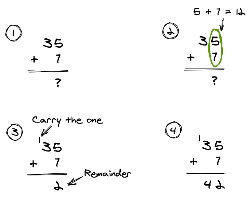
In the above example the addition in the units column is 5 plus 7 which equals 12. The result for the units column is 2 and we carry the 1 to the tens column.
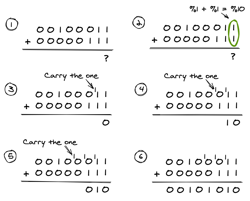
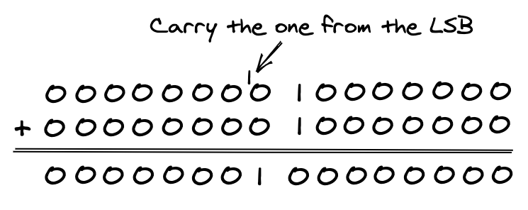
This all still holds when adding binary numbers. The difference is that we carry the one to the left for each column where the total is 2 or greater (%10 in binary). Here is the same addition performed using unsigned byte values:
When adding binary numbers, it is not always the case that the result can fit into one byte. The following example demonstrates adding $80 (128 in decimal) to itself:
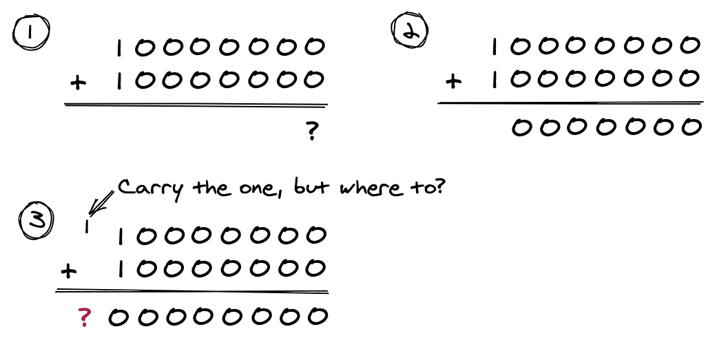
There is a 9th bit, a carry bit, that is not included in the result. To capture the full result we have to use 16-bit values in the calculation. We carry that 9th bit from the LSB to bit #0 of the MSB:
But because the 6502 is an 8-bit CPU, we can only add byte values. The solution is to combine multiple additions. We start with the LSBs and finish with the MSBs, including any carry bits in the calculations. For example, to add $80FF and $0003 (33,023 + 3 in decimal) we first add the LSBs, $FF and $03. The result is $02 plus a carry bit. Next we add the MSBs, $80 and $00, making sure to also add $01 for that carry bit. The result is $81 with no carry bit, so the combined result is $8102 or 33,026 in decimal. This is a complete result because no carry bit was left after adding the MSBs.
Now let us try adding $FFFE and $0003 (65,534 + 3 in decimal). First we add the LSBs, $FE and $03. The result is $01 plus a carry bit. Next we add the MSBs, $FF and $00, making sure to also add $01 for that carry bit. The result is $00 plus a carry bit. The combined result is $0001 (1 in decimal) but this is not the correct result (which would be 65,537 in decimal). A carry bit remains. We would have to perform this calculation using 24-bit values to get the full result.
Adding signed binary values
Adding signed binary values introduces the problem of overflow. As an example, let us try adding the signed byte value %01000000 (+64 in decimal) to itself:
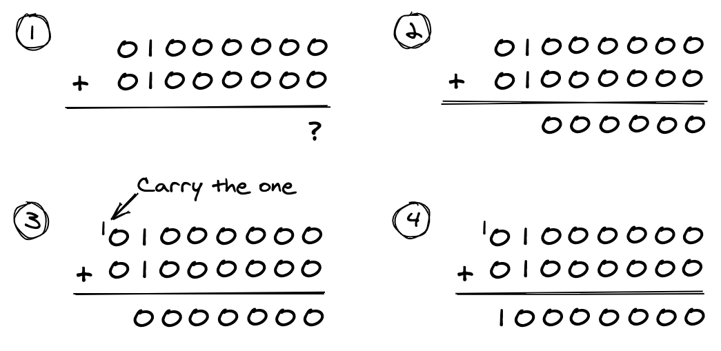
The result is %10000000, or 128 in decimal. This would be the correct answer if we were adding unsigned values, but we are not. This result actually represents -128 in two's complement representation. The problem is that bit #7 in a signed byte is reserved for the value's sign. Thus there is one less bit with which to represent a value's magnitude. A signed byte value can only represent values in the range -128 to +127. The correct answer of +128 lies outside that range. The result has overflowed the available magnitude bits.
When we were adding unsigned binary values, we could detect an invalid result. There was a carry bit remaining after adding the MSBs. How can we detect overflow when adding signed bytes? We have to see if the sign bit of the result is correct given the values that we have added together. In the example above we added two positive numbers, +127 and +2, so we would expect the result to be positive as well. In fact the result is negative because bit #7 of the result is set. Using this technique, we can identify the result as invalid.
More generally, when adding a negative value to a positive value or a positive value to a negative value, overflow cannot occur. But when the result of adding two positive values is negative or the result of adding two negative values is positive, overflow has occurred.
It is important to note that a remaining carry bit does not show an invalid result in the way that it does when adding unsigned values. You should in fact ignore any remaining carry bit when adding signed values.
We have to use 16-bit signed values in the above calculation to get the correct result. As you might expect, we have to add signed multi-byte values one byte pair at a time. We start with the LSBs and finish with the MSBs, and include any carry bits in the calculations. When performing the final addition of the MSBs, we need to check for overflow to ensure that the result is valid. We also ignore any carry bit that remains from this final addition.
To illustrate adding 16-bit signed values, let us add $80FF and $FFFE (-32,513 + -2 in decimal). We first add the LSBs, $FF and $FE. The result is $FD plus a carry bit. Next we add the MSBs, $80 and $FF, making sure to also add $01 for the carry bit. The result is $80 with a carry bit. We can ignore the carry bit, so the combined result is $80FD, or -32,515 in decimal. Now we need to check if overflow occurred. We added two negative values so the result should be negative too. The result $80FD does indeed represent a negative value (bit #7 of the MSB is set). Overflow has not occurred and the result is valid.
The implementation of addition in the 6502
We perform mathematical operations using the 6502's arithmetic logic unit (ALU). The 6502 includes a Carry flag that it uses in two ways:
- During addition it indicates if the ALU should add one to the current addition calculation. The ALU will add one when the flag is set.
- The ALU updates the Carry flag after an addition to indicate if the result includes a carry bit. If the Carry flag is set then the result includes a carry bit, but if the Carry flag is not set then it does not.
We use the addition operation to add two byte values. The calculation that the ALU performs is the following:
Byte1 + Byte2 + Carry
Carry has the value one if the Carry flag is set, or zero if it is not.
When starting an addition operation, we must first ensure that the Carry flag is not set. When adding multi-byte values, we must only do this before we add the first byte pair. We must not update the state of the Carry flag as we proceed to add the other byte pairs. This way any carry bit generated by adding one byte pair gets carried over into the addition of the next byte pair.
Subtracting binary values
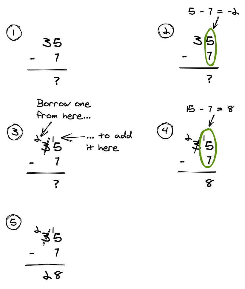
In subtraction, we call the number we are subtracting from the minuend. We call the number we are subtracting by the subtrahend.
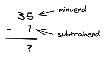
When we subtract two decimal numbers, we subtract the digits column by column, from right to left. For each column where the result would be negative, we have to borrow one from the next column to the left:
This all holds when subtracting binary values. The following shows subtracting 7 from 11 in binary:
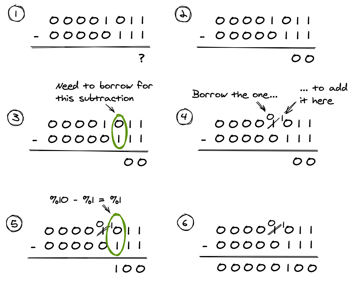
As you can see, borrowing still applies as necessary.
Subtraction as addition
As noted before, the ALU performs the mathematical operations. Creating an ALU that supports both addition and subtraction adds to its complexity. There is an alternative approach. We can implement subtraction as addition if we negate the subtrahend and then add it to the minuend. This is best illustrated with an example. Let us say that we want to calculate +35 - +7, which equals +28. If we negate the subtrahend then it changes value from +7 to -7. By adding it to the minuend, the calculation now becomes +35 + -7. We still get the correct answer of +28.
For this technique to work in the binary world of the 6502, we need to know how to negate a signed binary value. As explained earlier, the 6502 uses the two's complement representation for signed values. Thus the following negation algorithm applies:
- Find the one's complement of the number.
- Add one.
Finding the one's complement of a binary value means inverting its bits. All the ones become zeros and all the zeros become ones. The symbol for taking the one's complement of a number is the tilde (~).
Let us try calculating +35 - +7 again but this time in binary. Using the two's complement representation, this is %00100011 - %00000111. The one's complement of the subtrahend is %11111000, or -8 in decimal. We add one to it, to give %11111001, or -7 in decimal. The subtraction now becomes an addition: %00100011 + %11111001, or +35 + -7.
There is a wrinkle to how the ALU implements this. As shown earlier, the ALU implements addition like so:
Byte1 + Byte2 + Carry
The ALU implements subtraction in the same way but with a single change — it takes the one's complement of the subtrahend:
Byte1 + ~Byte2 + Carry
Thus it is the Carry flag which controls whether the 'add one' stage of the negation process is performed. Normally we want to add one, and so we have to ensure that the Carry flag is set before a subtraction operation. For example, let us calculate $02 - $01, which is +2 - +1 in decimal. The ALU transforms this into the following calculation:
  Byte1 + ~Byte2 + Carry
= $02 + ~$01 + Carry
= $02 + $FE + Carry
= $00 + Carry
The correct answer to the calculation is $01 or 1 in decimal. We only get the correct answer if the Carry flag is set:
  Byte1 + ~Byte2 + Carry
= $02 + ~$01 + $01
= $02 + $FE + $01
= $00 + $01
= $01
Thus, before performing a subtraction operation, we have to ensure that the Carry flag is set.
As explained before, the ALU updates the Carry flag after an addition operation to show whether the result includes a carry bit. For a subtraction operation, the ALU updates the Carry flag to indicate whether it had to borrow a bit. It is important to note that in this case, the Carry flag is set inversely by the ALU:
- If the Carry flag is set then the ALU did not need to borrow a bit.
- If the Carry flag is not set then the ALU had to borrow a bit.
With the previous calculation of $02 - $01, the Carry flag is set after the subtraction. This is because the result of adding $02 + $FE + $01 is $01 and a carry bit. The carry bit indicates that a bit was not borrowed, which is correct.
Let us try a calculation where a bit needs to be borrowed. For this, let us calculate $02 - $03, which is +2 - +3 in decimal. The ALU transforms this into the following calculation:
  Byte1 + ~Byte2 + Carry
= $02 + ~$03 + $01
= $02 + $FC + $01
= $FE + $01
= $FF
The result of adding $02 + $FC + $01 is $FF with no carry bit, so the Carry flag is not set after this subtraction operation. If we were to actually perform this operation as a subtraction then we would need to borrow one. That is why the Carry flag not being set indicates that the ALU had to borrow a bit.
To get a complete result, we would have to perform this subtraction using 16-bit signed values, as $0002 - $0003. As with adding multi-byte values, we have to perform the operation one byte pair at a time. We start with the LSBs and finish with the MSBs. We first ensure that the Carry flag is set before starting the subtraction process. We have already seen the subtraction of the LSBs ($02 - $03):
  $02 + ~$03 + Carry
= $02 + ~$03 + $01
= $02 + $FC + $01
= $FE + $01
= $FF
The result is $FF with no carry bit. Now we can add the MSBs. We do not update the value of the Carry flag during the subtraction operation. The ALU performs the following calculation:
  $00 + ~$00 + Carry
= $00 + ~$00 + $00
= $00 + $FF + $00
= $FF + $00
= $FF
Thus the final answer is $FFFF with no carry bit. This is -1 in decimal when using the two's complement representation for binary values. As the Carry flag was not set in the MSB calculation, we did not add one. This accounted for the fact that one had to be borrowed from that byte pair.
Let us see how this works for some more multi-byte signed values. First let us calculate +255 - -1, which is $00FF - $FFFF in hex. We subtract the LSBs, $FF - $FF. This gets rewritten using addition as $FF + ~$FF + Carry. Carry is $01 because that is its required initial value. This simplifies to $FF + $00 + $01, which equals $00 with a carry bit. Now we subtract the MSBs, $00 - $FF. This gets rewritten using addition as $00 + ~$FF + Carry. Here Carry is $01 because there was a carry bit generated from adding the LSBs. This simplifies to $00 + $00 + $01, which equals $01 with no carry bit. Thus the combined result is $0100, or +256 in decimal.
Now let us calculate +256 - +1, which is $0100 - $0001 in hex. We subtract the LSBs, $00 - $01. This gets rewritten using addition as $00 + ~$01 + Carry. Carry is $01 because that is its required initial value. This simplifies to $00 + $FE + $01, which equals $FF with no carry bit. Now we subtract the MSBs, $01 - $00. This gets rewritten using addition as $01 + ~$00 + Carry. Here Carry is $00 as there was no carry bit generated from adding the LSBs. This simplifies to $01 + $FF + $00, which equals $00 with a carry bit. We know to ignore that final carry bit because we are adding signed values. The combined result is $00FF, or +255 in decimal.
In both cases, we need to ensure that overflow has not occurred when adding the MSBs. The rule for overflow when subtracting is different to the rule for overflow when adding. When subtracting two numbers, overflow occurs when their signs differ and the sign of the result is the same as the sign of the subtrahend. In the example of +255 - -1 the signs do differ, but the result (+256) is positive while the subtrahend (-1) is negative. Thus overflow has not occurred. In the case of the example of +256 - +1, the signs are the same and so overflow cannot occur.
Increasing bit counts
When adding or subtracting two values, they should have the same bit count. If this is not the case then you need to add bits to the most significant side of the shorter value. You need to make it equal in length to the longer value. But you need to do this in a way that does not change the value being represented.
This is easy to do for unsigned values: you add as many significant zero bits as required. For example, you can convert the 8-bit unsigned value %11111111 (255 in decimal) into a 16-bit value by prepending eight zero bits. This gives the value %0000000011111111.
The approach is not as obvious for signed values. The solution is sign extension. You still add as many significant bits as necessary, but all the added bits have the same value as the sign bit. For example, the value -128 as an 8-bit signed value is %10000000. The sign bit (bit #7) has the value 1 so you form the 16-bit signed value by adding an MSB with all its bits set to 1. This gives the value %1111111110000000, which still represents -128 in decimal.
Best practise for addition and subtraction
Bear the following in mind when adding or subtracting binary values:
- Avoid mixing signed and unsigned values. At the very least it is difficult to know when overflow has occurred and how any carry bits should be handled.
- The two values to add or subtract should have the same bit count. You should sign-extend the shorter value if this is not the case.
- Ignore any carry bit that remains after adding adding or subtracting signed values. But you do need to check for overflow.
Processor registers
The 6502 has six processor registers. These are special data storage areas that are separate from the CPU's address space. These registers allow the 6502 to execute instructions faster than it could if it only had access to system RAM. Each has a special role within the CPU.
The six registers, along with their abbreviations, are:
- The Program Counter (PC).
- The Stack Pointer (S).
- The Processor Status (P).
- The Accumulator (A).
- Index Register X (X).
- Index Register Y (Y).
The Program Counter (PC) stores the address of the next instruction to be executed. The CPU automatically updates that address as it sequentially executes your program. You can also use instructions to update the value of the Program Counter to a particular address.
This register is two bytes in size because the Program Counter stores an address. (The 6502 uses 16-bit addresses.) The rest of the registers each hold a single data value and, since the 6502 has an 8-bit data bus, all are one byte in size.
The Accumulator (A) is the main register that instructions operate on. Many instructions use it in their inputs or write their result to it. It is also useful as a temporary storage area when moving data from one memory location to another.
Index Register X (X) and Index Register Y (Y) are more simply called the X register and the Y register. Each can be used to specify a particular byte in the address space for an instruction to operate on. The address of that byte is the sum of some base address and the current value in the register. For example, an instruction might using the X register with a base address of $0C01. If the current value in the X register is $02 then the address accessed by the instruction will be $0C03 ($0C01 plus $02). Indexing in this way is useful when you want to iterate through a sequence of bytes in memory. You can also use these index registers as temporary storage areas.
The Stack Pointer (S) is used to point to the next free byte in the 6502's call stack. I cover the call stack in detail later in this post.
Finally there is the Processor Status (P) register. This register actually operates as eight flag bits. Each bit indicates if some particular processor status is currently true or not. A bit is set if it is a one, and clear or not set if it is a zero. Only seven out of the eight flag bits are used; bit #5 is unused.
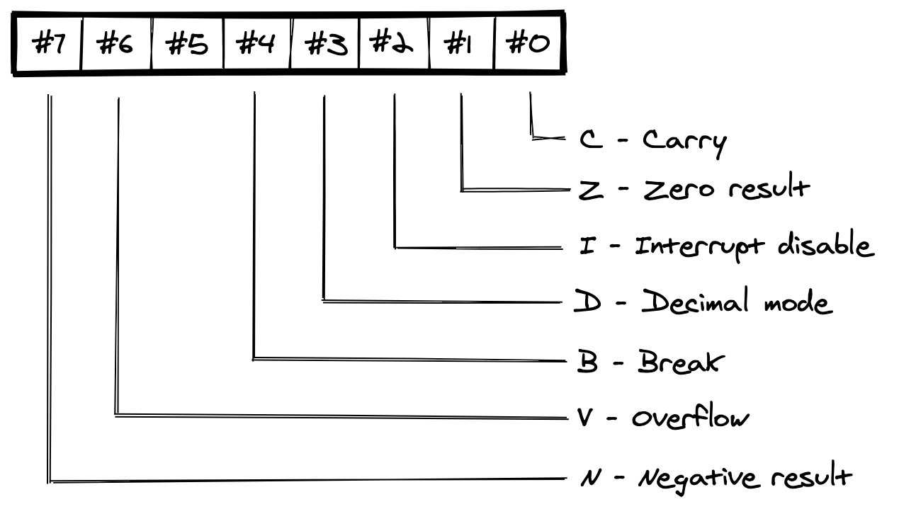
The Carry (C) flag is used by the ALU as a carry or borrow bit for addition and subtraction. The ALU also uses it as a ninth bit for the bit shifting operations.
Before an addition, you need to set the Carry flag if it should include a carry bit or clear it if it should not. The ALU then updates this flag when the addition operation is complete. It gets set if the result of the addition includes a carry bit, and it gets cleared if the result does not.
Before a subtraction, you need to set the Carry flag if it should not include a borrow bit or clear it if it should. The ALU then updates this flag when the subtraction operation is complete. It gets set if it did not need to borrow a bit, and it gets cleared if it did.
(The borrowing is conceptual since the ALU turns subtraction into addition.)
The Negative (N) flag is useful when values are being interpreted as signed values. The most significant bit (the sign bit) indicates if the value is positive or negative. Some instructions update this flag to the same state as bit #7 of the instruction result. If we know that the instruction result is the MSB of a signed value, this flag indicates if the value is positive or negative.
The ALU sets the Overflow (V) flag when the sign bit of the result of an addition or subtraction does not have the expected state. This is specifically when the values being added or subtracted are interpreted as signed 8-bit values. It is only useful to check for overflow after adding or subtracting the MSBs of two signed values. If the Overflow flag is set then overflow has occurred and the result is not valid. If this flag is not set then overflow has not occurred.
The Overflow and Negative flags are useful if you want to check the state of bit #6 or bit #7 of some byte. For example, you can use a BIT instruction to do this for any byte in memory (as discussed later in this post). These flags makes these bit positions cheap to test. Any flag bytes in your program should generally use bit #6 or bit #7 for the flags that you will check most.
The Zero (Z) flag is set by some instructions if the result of the instruction is zero (i.e., $00). For example, subtracting $04 from $04 equals $00, which would result in the Zero flag being set.
The Interrupt Disable (I) flag indicates if maskable interrupts are disabled or enabled. They are disabled when the flag is set and enabled when the flag is not set. I cover interrupts later in this post.
The CPU updates the Break (B) flag as appropriate. It is useful in an interrupt handler if you need to determine how an interrupt was triggered. It could have been because of a BRK instruction or a normal maskable interrupt.
The Decimal Mode (D) flag is used to control if the CPU is in binary coded decimal mode or not. The flag can be set and cleared, but this has no effect on the CPU's operation. The CPU used in the NES does not implement this mode.
Addressing modes
A program instruction represents a particular operation on a particular byte of data. The instruction's three-letter mnemonic determines the particular operation. The byte of data to operate on can be specified in several ways. Each means of specifying that byte of data is termed an addressing mode. The 6502 has thirteen such modes:
- Implied
- Accumulator
- Immediate
- Absolute
- Zero Page
- Absolute, X
- Absolute, Y
- Zero Page, X
- Zero Page, Y
- (Indirect, X)
- (Indirect), Y
- Absolute Indirect
- Relative
Each of the 6502's operations support one or more of these addressing modes.
In the Implied addressing mode, it is the operation itself that implies the byte to operate on. For example, the CLC (Clear Carry Flag) operation clears the Carry flag of the Processor Status register. The byte to operate on — the Processor Status register — is implied; you cannot specify a different byte of data.
Related to the implied addressing mode is the Accumulator addressing mode. This takes the form <mnemonic> A. It specifies that the byte to operate on is the value in the Accumulator (hence 'A').
Instructions that use the Implied or Accumulator addressing modes are always one byte long because they have no operand. The rest of the addressing modes need an operand to specify the byte of data to operate on. I will mainly use the LDA (Load Accumulator with memory) operation to illustrate these addressing modes. It is used to load a byte of data from memory into the Accumulator.
The Immediate addressing mode takes the form <mnemonic> #<some_byte_value>. The <some_byte_value> is the byte to operate on. It is embedded in the instruction. An instruction that uses this addressing mode will be two bytes long: one byte for the opcode and one byte for the embedded byte value. The following example loads the value $04 into the Accumulator:
LDA #$04
The Absolute addressing mode takes the form <mnemonic> <some_address>. The <some_address> is a two-byte address in the CPU's address space. It is the byte at this address that will be operated on. An instruction that uses this addressing mode will be three bytes long: one byte for the opcode and two bytes for the address. The following example loads the byte at address $027E into the Accumulator:
LDA $027E
A variation on the absolute addressing mode is the Zero Page addressing mode. This takes the form <mnemonic> $<some_byte_value>. The <some_byte_value> specifies an address within the zero page. The zero page is the first 256 bytes of the CPU's address space, from addresses $0000 to $00FF. The most significant byte of a zero page address will always be $00. Thus we only need a single byte to specify an address within it. It is the byte at this address that will be operated on. An instruction that uses this addressing mode will be two bytes long: one byte for the opcode and one byte for the address LSB. The following example loads the byte at address $007E into the Accumulator:
LDA $7E
You could have used the Absolute addressing mode to load this byte, using the instruction LDA $007E. But there are advantages to the Zero Page addressing mode:
- The instruction is smaller, being two bytes rather than three.
- The instruction will take one less cycle to execute.
The 6502 has relatively few registers. The Zero Page addressing mode compensates somewhat for this by making the zero page more efficient to access than the rest of system RAM. Because of this, you should store your most accessed values in the zero page.
There are four addressing modes that are indexed variations of the Absolute and Zero Page addressing modes. They are Absolute, X, Absolute, Y, Zero Page, X, and Zero Page, Y. For each, the address of the byte to operate on is found by adding the current value in the X or Y register to the address specified in the instruction. Thus the address in the instruction is the base address to which the CPU adds an index value. This gives the final address of the byte to operate on. (This usage is the reason why we call the X and Y registers the index registers.) We show this mode by appending , X or , Y as appropriate.
The following example instructions demonstrate these four modes:
LDA $027E, X  ; Absolute, X
LDA $7E, X    ; Zero Page, X
LDA $027E, Y  ; Absolute, Y
LDA $7E, Y    ; Zero Page, Y
These indexed addressing modes are useful when you want to loop through some part of the address space. They allow you to write fewer instructions compared to an unrolled loop, at the expense of increased execution time. But be aware: in the zero page form the result is always an address within the zero page. For example, if the instruction LDA $FF, X is executed when the X register contains the value $02, then the address accessed is not $0101 ($FF + $02). It is instead $0001. Only the LSB of the address changes when indexing within the zero page.
Up to now, the addressing modes that specify an address have done so by hard-coding it. But what if it is only at runtime that you will know the address to use? What if you want to have a pointer to the code to execute when some user action occurs? What if you want to sometimes change that pointer at runtime to point to different code? These are the scenarios that the various indirect addressing modes support.
There are two indexed indirect addressing modes. The first one is the (Indirect, X) addressing mode and it takes the form <mnemonic> (<some_byte_value>, X). The <some_byte_value> specifies an address within the zero page. The value in the X register is added to this address. The result again specifies an address within the zero page. The byte of data at this adjusted address is then read, along with the byte after it. The two bytes are interpreted respectively as the LSB and MSB of an address somewhere in the CPU's address space. It is this final address that identifies the byte of data the instruction should operate on.
The following is an example instruction that uses this addressing mode:
LDA ($04, X)
The address specified represents the address $0004. The CPU first adds the current value in the X register to it. If the value in the X register is $02 then the resulting address will be $0006. The CPU now reads the value of the byte at address $0006 and the value of the byte after it. It combines them to create a two-byte address. If the value of the byte at address $0006 is $34 and the value of the byte at address $0007 is $12 then the result will be $1234. This is the address that identifies the byte of data that the instruction should operate on. In this example, it is the byte in memory at address $1234 that the CPU will load into the Accumulator.
Note that adding the value in the X register to the zero page address always gives another zero page address. Only the LSB of the address gets adjusted. This is the same as with the Zero Page, X and Zero Page, Y addressing modes. For example, if the instruction is LDA ($FF, X) and the value in the X register is $00, then the CPU reads the value of the bytes at addresses $00FF and $0000. It does not read the bytes at addresses $00FF and $0100.
The second indexed indirect addressing mode is the (Indirect), Y addressing mode. It takes the form <mnemonic> (<some_byte_value>), Y. The <some_byte_value> again specifies an address within the zero page, but indexing behaves differently. The CPU reads the byte of data at this zero page address along with the byte after it. It interprets the two bytes respectively as the LSB and MSB of a base address somewhere in the CPU's address space. The value in the Y register is then added to this base address. This creates the final address of the byte of data that the instruction should operate on.
The following is an example instruction that uses this addressing mode:
LDA ($04), Y
The address specified represents the address $0004. The CPU reads the value of the byte at address $0004 and then reads the value of the byte after it. It combines them to create a two-byte address. If the value of the byte at address $0004 is $34 and the value of the byte at address $0005 is $12, the resulting address is $1234. The CPU now adds the value in the Y register to this address. If the value in the Y register is $02 then the result will be $1236. This is the address that identifies the byte of data that the instruction should operate on. In this example, the CPU will load the byte in memory at address $1236 into the Accumulator.
If the zero page address specified in the instruction is $FF, the CPU reads the bytes at addresses $00FF and $0000. It does not read the bytes at addresses $00FF and $0100.
There is a third indirect addressing mode, the Absolute Indirect addressing mode. It is only used with the JMP operation. It takes the form JMP (<some_address>) (note the parentheses). The <some_address> is an address in the CPU's address space. At runtime, the CPU reads the byte of data at this address along with the byte after it. The CPU interprets these two bytes respectively as the LSB and MSB of an address that it uses to update the Program Counter.
The following is an example JMP instruction that uses this addressing mode:
JMP ($1234)
The CPU reads the value of the byte at address $1234 and the value of the byte after it. It combines them to create a two-byte address. If the value of the byte at address $1234 is $78 and the value of the byte at address $1235 is $56, the resulting address is $5678. This is the address that the CPU updates the Program Counter to. Program execution now jumps to that address.
The final addressing mode is the Relative addressing mode. This is an addressing mode used exclusively by the branch operations. (I cover those operations later in this post.) This mode takes the form <mnemonic> <some_signed_byte_value>. The some_signed_byte_value is a single byte that the CPU interprets as a two's complement signed value. The magnitude of this value indicates by how much the CPU should adjust the Program Counter by. Its sign indicates if the adjustment should be forwards (a positive value) or backwards (a negative value). Program execution then continues from the adjusted address.
BMI $7F ; Jump forward 127 bytes if the branch condition is true.

BMI $80 ; Jump backward 128 bytes if the branch condition is true.
Normally you would use a label as the operand:
BMI some_label ; Jump forward or backward to some_label
               ; if the branch condition is true.
Since a single signed byte value is used to indicate the adjustment, it can only be in the range -128 to +127. You cannot adjust the Program Counter beyond this range. This includes when using a label. I discuss this restriction when I cover branching.
The operations in detail
The 6502 supports 151 opcodes, grouped into 56 operations. I summarise each operation in this section. This includes its addressing modes and how it updates the Process Status register.
Running the assembly code examples
I include examples of 6502 assembly to show various algorithms and patterns. You can run most of them as-is in a 6502 emulator. The easiest one to use this browser-based 6502 emulator. Note that it has limitations, such as not supporting binary literals and constants.
To use the emulator:
- Copy and paste or manually enter the assembly code into the large text area.
- Click the Assemble button. You can check for any assembler errors in the message box at the bottom of the page.
- Click the Run button to run the program.
It shows the state of the registers after the program runs in the righthand column. To see the state of the system RAM, tick the Monitor option below the text area.
Operations for setting and clearing the Processor Status register flags
Some of the Processor Status register flags can be set and/or cleared by the programmer. This is generally only useful in specific situations. Examples include before addition and subtraction, and when handling an interrupt. I have included the operations for setting and clearing the Decimal Mode flag. Remember that the CPU in the NES does not support that mode.
SEC (Set Carry Flag)
Sets the Carry flag of the Processor Status register.
Supported addressing modes
| Addressing mode | Example instruction |
|---|---|
| Implied | SEC |
CLC (Clear Carry Flag)
Clears the Carry flag of the Processor Status register.
Supported addressing modes
| Addressing mode | Example instruction |
|---|---|
| Implied | CLC |
CLV (Clear Overflow Flag)
Clears the Overflow flag of the Processor Status register.
Supported addressing modes
| Addressing mode | Example instruction |
|---|---|
| Implied | CLV |
SEI (Set Interrupt Disable Flag)
Sets the Interrupt Disable flag of the Processor Status register.
Supported addressing modes
| Addressing mode | Example instruction |
|---|---|
| Implied | SEI |
CLI (Clear Interrupt Disable Flag)
Clears the Interrupt Disable flag of the Processor Status register.
Supported addressing modes
| Addressing mode | Example instruction |
|---|---|
| Implied | CLI |
SED (Set Decimal Mode)
Sets the Decimal Mode flag of the Processor Status register.
Supported addressing modes
| Addressing mode | Example instruction |
|---|---|
| Implied | SED |
CLD (Clear Decimal Mode)
Clears the Decimal Mode flag of the Processor Status register.
Supported addressing modes
| Addressing mode | Example instruction |
|---|---|
| Implied | CLD |
Operations for transferring bytes of data
Many of the instructions in your programs will be for shuffling data around. This is because very few operations mutate data in place in memory. You need to instead load a value into a register, operate on it, and then store the result somewhere.
The following diagram shows the supported transfers:
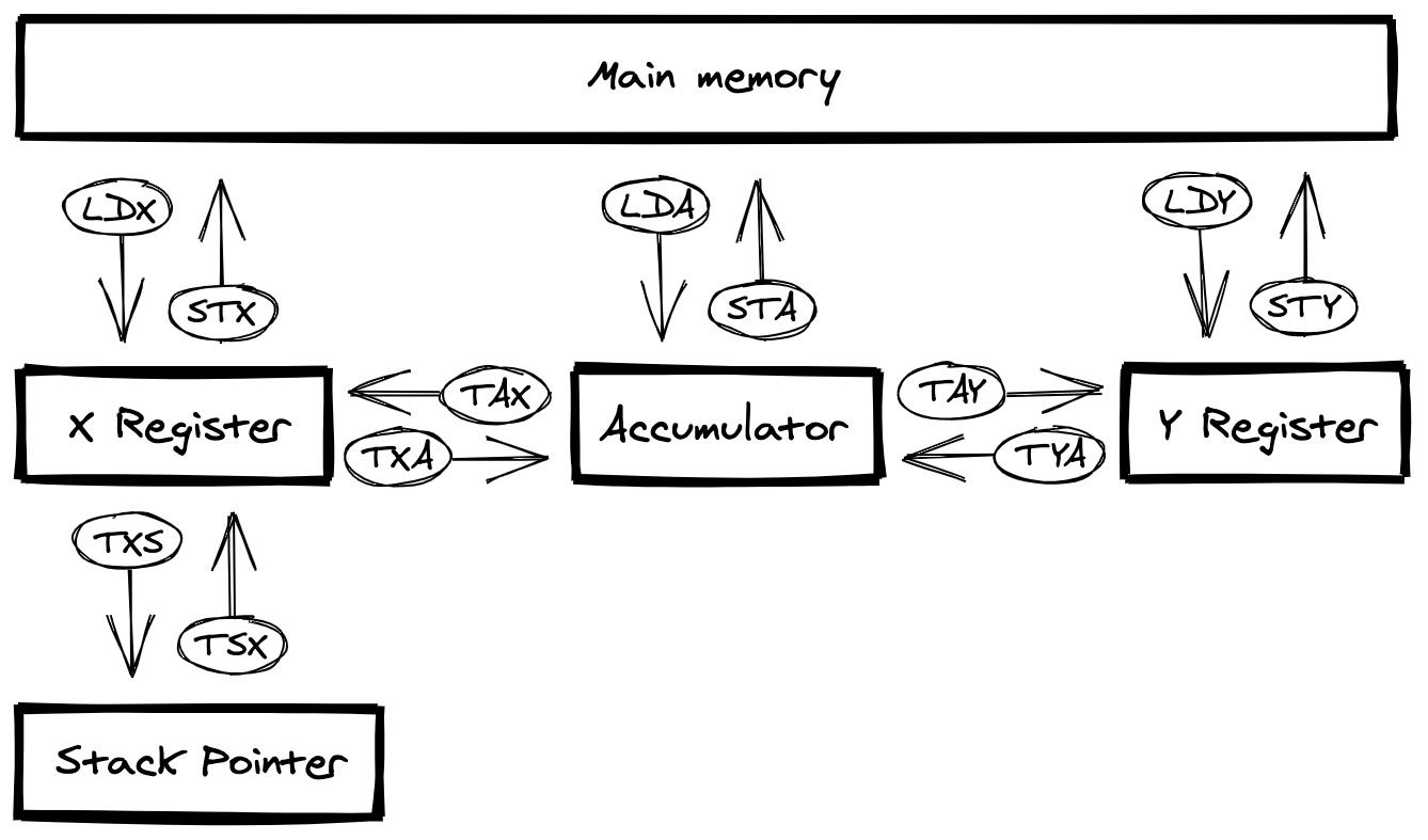
As this diagram shows, it is not possible to transfer directly between the X and Y registers.
LDA (Load Accumulator with memory)
Loads the specified byte into the Accumulator.
Processor Status register changes
| Flag | Effect |
|---|---|
| Zero flag | Set if the specified byte is zero, otherwise cleared. |
| Negative flag | Updated to the value of bit #7 of the specified byte. |
Supported addressing modes
| Addressing mode | Example instruction |
|---|---|
| Immediate | LDA #$00 |
| Absolute | LDA $0000 |
| Zero Page | LDA $00 |
| Absolute, X | LDA $0000, X |
| Absolute, Y | LDA $0000, Y |
| Zero Page, X | LDA $00, X |
| (Indirect, X) | LDA ($00, X) |
| (Indirect), Y | LDA ($00), Y |
LDX (Load Index Register X with memory)
Loads the specified byte into the X register.
Processor Status register changes
| Flag | Effect |
|---|---|
| Zero flag | Set if the specified byte is zero, otherwise cleared. |
| Negative flag | Updated to the value of bit #7 of the specified byte. |
Supported addressing modes
| Addressing mode | Example instruction |
|---|---|
| Immediate | LDX #$00 |
| Absolute | LDX $0000 |
| Zero Page | LDX $00 |
| Absolute, Y | LDX $0000, Y |
| Zero Page, Y | LDX $00, Y |
LDY (Load Index Register Y with memory)
Loads the specified byte into the Y register.
Processor Status register changes
| Flag | Effect |
|---|---|
| Zero flag | Set if the specified byte is zero, otherwise cleared. |
| Negative flag | Updated to the value of bit #7 of the specified byte. |
Supported addressing modes
| Addressing mode | Example instruction |
|---|---|
| Immediate | LDY #$00 |
| Absolute | LDY $0000 |
| Zero Page | LDY $00 |
| Absolute, X | LDY $0000, X |
| Zero Page, X | LDY $00, X |
STA (Store Accumulator in memory)
Copies the value in the Accumulator to the specified memory location.
Processor Status register changes
Does not update any flags.
Supported addressing modes
| Addressing mode | Example instruction |
|---|---|
| Absolute | STA $0000 |
| Zero Page | STA $00 |
| Absolute, X | STA $0000, X |
| Absolute, Y | STA $0000, Y |
| Zero Page, X | STA $00, X |
| (Indirect, X) | STA ($00, X) |
| (Indirect), Y | STA ($00), Y |
STX (Store Index Register X in memory)
Copies the value in the X register to the specified memory location.
Processor Status register changes
Does not update any flags.
Supported addressing modes
| Addressing mode | Example instruction |
|---|---|
| Absolute | STX $0000 |
| Zero Page | STX $00 |
| Zero Page, Y | STX $00, Y |
STY (Store Index Register Y in memory)
Copies the value in the Y register to the specified memory location.
Processor Status register changes
Does not update any flags.
Supported addressing modes
| Addressing mode | Example instruction |
|---|---|
| Absolute | STY $0000 |
| Zero Page | STY $00 |
| Zero Page, X | STY $00, X |
TAX (Transfer Accumulator to Index Register X)
Copies the value in the Accumulator to the X register.
Processor Status register changes
| Flag | Effect |
|---|---|
| Zero flag | Set if the copied byte is zero, otherwise cleared. |
| Negative flag | Updated to the value of bit #7 of the copied byte. |
Supported addressing modes
| Addressing mode | Example instruction |
|---|---|
| Implied | TAX |
TAY (Transfer Accumulator to Index Register Y)
Copies the value in the Accumulator to the Y register.
Processor Status register changes
| Flag | Effect |
|---|---|
| Zero flag | Set if the copied byte is zero, otherwise cleared. |
| Negative flag | Updated to the value of bit #7 of the copied byte. |
Supported addressing modes
| Addressing mode | Example instruction |
|---|---|
| Implied | TAY |
TXA (Transfer Index Register X to Accumulator)
Copies the value in the X register to the Accumulator.
Processor Status register changes
| Flag | Effect |
|---|---|
| Zero flag | Set if the copied byte is zero, otherwise cleared. |
| Negative flag | Updated to the value of bit #7 of the copied byte. |
Supported addressing modes
| Addressing mode | Example instruction |
|---|---|
| Implied | TXA |
TYA (Transfer Index Register Y to Accumulator)
Copies the value in the Y register to the Accumulator.
Processor Status register changes
| Flag | Effect |
|---|---|
| Zero flag | Set if the copied byte is zero, otherwise cleared. |
| Negative flag | Updated to the value of bit #7 of the copied byte. |
Supported addressing modes
| Addressing mode | Example instruction |
|---|---|
| Implied | TYA |
The two operations below are for data transfers between the X register and the Stack Pointer. I cover their usage later in this post in the section on the call stack.
TXS (Transfer Index Register X to Stack Pointer)
Copies the value in the X register to the Stack Pointer.
Processor Status register changes
Does not update any flags.
Supported addressing modes
| Addressing mode | Example instruction |
|---|---|
| Implied | TXS |
TSX (Transfer Stack Pointer to Index Register X)
Copies the value in the Stack Pointer to the X register.
Processor Status register changes
| Flag | Effect |
|---|---|
| Zero flag | Set if the copied byte is zero, otherwise cleared. |
| Negative flag | Updated to the value of bit #7 of the copied byte. |
Supported addressing modes
| Addressing mode | Example instruction |
|---|---|
| Implied | TSX |
The following assembly demonstrates how you can use these data transfer operations. I store a given 16-bit value in memory and then copy it to another memory location:
; Store the 16-bit value $0123 into system RAM, in little endian format.

LDA #$23  ; Load LSB as an immediate value into the Accumulator.
STA $00   ; Store the Accumulator in memory at address $0000.
LDA #$01  ; Load MSB as an immediate value into the Accumulator.
STA $01   ; Store the Accumulator in memory at address $0001.

; Copy that value to another location in system RAM.

LDA $00   ; Load LSB from address $0000 into the Accumulator.
STA $02   ; Store the Accumulator in memory at address $0002.
LDA $01   ; Load MSB from address $0001 into the Accumulator.
STA $03   ; Store the Accumulator in memory at address $0003.
After this code runs, the sequence of bytes at the start of the zero page is now $23 $01 $23 $01.
Addition
Addition is performed using the ADC operation.
ADC (Add memory to Accumulator with Carry)
Adds three values together: the current value in the Accumulator, the byte value specified by the operand, and the Carry flag. The result of the addition is stored in the Accumulator.
Processor Status register changes
| Flag | Effect |
|---|---|
| Carry flag | Set if the result includes a carry bit, otherwise cleared. |
| Overflow flag | Set if bit #7 of the result changed in a way that indicates overflow when adding signed byte values, otherwise cleared. |
| Zero flag | Set if the result is zero, otherwise cleared. |
| Negative flag | Updated to the value of bit #7 of the result. |
Supported addressing modes
| Addressing mode | Example instruction |
|---|---|
| Immediate | ADC #$00 |
| Absolute | ADC $0000 |
| Zero Page | ADC $00 |
| Absolute, X | ADC $0000, X |
| Absolute, Y | ADC $0000, Y |
| Zero Page, X | ADC $00, X |
| (Indirect, X) | ADC ($00, X) |
| (Indirect), Y | ADC ($00), Y |
The following assembly demonstrates adding together two 8-bit unsigned values:
; $FE + $01 (254 + 1 in decimal)

CLC       ; Clear the Carry flag.
LDA #$FE  ; Load $FE as an immediate value into Accumulator.
STA $00   ; Store Accumulator in memory at address $0000.
LDA #$01  ; Load $01 as an immediate value into Accumulator.
ADC $00   ; Add value at address $0000 to the Accumulator.
After this code runs, the value in the Accumulator is now $FF and the Carry flag is not set. Thus there is no carry bit and the result still fits into one byte.
The CLC instruction in the example above is important. Before starting an addition operation, you need to ensure that the Carry flag is not set. If it is, the result will be incorrect. (It is possible for the Carry flag to be set if, say, a previous addition or subtraction operation set it.)
The following assembly demonstrates adding two 8-bit unsigned values. In this case the result will not fit into a single byte:
; $FE + $03 (254 + 3 in decimal)

CLC       ; Clear the Carry flag.
LDA #$FE  ; Load $FE as an immediate value into the Accumulator.
STA $00   ; Store Accumulator in memory at address $0000.
LDA #$03  ; Load $01 as an immediate value into the Accumulator.
ADC $00   ; Add value at address $0000 to the Accumulator.
After this code runs, the value in the Accumulator is $01 and the Carry flag is set. We are missing the 9th carry bit in the result. Instead we have to perform the calculation using 16-bit unsigned values:
; $00FE + $0003 (254 + 3 in decimal)

; Store LSB of first value in memory at address $0000.
LDA #$FE
STA $00

; Store MSB of first value in memory at address $0001.
LDA #$00
STA $01

; Store LSB of second value in memory at address $0002.
LDA #$03
STA $02

; Store MSB of second value in memory at address $0003.
LDA #$00
STA $03

CLC       ; Clear the Carry flag.

; Add the LSBs
LDA $00   ; Load LSB of first value into the Accumulator.
ADC $02   ; Add LSB of second value to the Accumulator.
STA $04   ; Store LSB of result in memory at address $0004.

; Add the MSBs, including the carry bit from the first addition.
LDA $01   ; Load MSB of first value into the Accumulator.
ADC $03   ; Add MSB of second value to the Accumulator.
STA $05   ; Store LSB of result in memory at address $0005.
The following assembly demonstrates adding two 8-bit signed values:
; $7E + $FB (+120 + -5 in decimal)

CLC       ; Clear the Carry flag.
LDA #$7E  ; Load $7E as an immediate value into the Accumulator.
STA $00   ; Store the Accumulator in memory at address $0000.
LDA #$FB  ; Load $FB as an immediate value into the Accumulator.
ADC $00   ; Add value at address $0000 to the Accumulator.
After this code runs, the Carry flag is set and the Overflow flag is not set. We are adding signed values so we are only interested in checking for overflow. Since the Overflow flag is not set, the result is valid. But if we change the above addition to $80 + $FB, or -128 + -5 in decimal, the Overflow flag would get set. Thus the result would be invalid. The answer is to use 16-bit signed values:
; $FF80 + $FFFB (-128 + -5 in decimal)

; Store LSB of -128 in memory at address $0000.
LDA #$80
STA $00

; Store MSB of -128 in memory at address $0001.
LDA #$FF
STA $01

; Store LSB of -5 in memory at address $0002.
LDA #$FB
STA $02

; Store MSB of -5 in memory at address $0003.
LDA #$FF
STA $03

CLC       ; First clear the Carry flag.

; Add the LSBs
LDA $00   ; Load LSB of first value into the Accumulator.
ADC $02   ; Add LSB of second value to the Accumulator.
STA $04   ; Store LSB of result in memory at address $0004.

; Add the MSBs, including any carry bit from the first addition.
LDA $01   ; Load MSB of first value into the Accumulator.
ADC $03   ; Add MSB of second value to the Accumulator.
STA $05   ; Store LSB of result in memory at address $0005.
Earlier I described how to use sign extension to add two signed values with different bit counts. Now I can show you how to add an 8-bit signed value — a delta value — to a 16-bit signed value, as discussed here. In the following assembly, I first sign-extend the delta value before the addition:
; $0030 + $9C = $FFCC
; In decimal: +48 + -100 = -52

; Store LSB of $0030 in memory at address $0000.
LDA #$30
STA $00

; Store MSB of $0030 in memory at address $0001.
LDA #$00
STA $01

; Store the delta value $9C in memory at address $0002.
LDA #$9C
STA $02

; Precalculate the sign-extended high byte of the delta value
; and store it in the X register.
; If delta is positive then we store an all zeros byte in the X register.
; If delta is negative then we store an all ones byte in the X register.

LDX #$00 ; Load $00 into the X register.
LDA $02  ; Load the delta value into the Accumulator.
BPL sign_extended ; Skip the decrement if the delta value is positive.
  DEX ; Decrementing zero by one results in a byte of all ones,
      ; which is the correct high byte for a negative delta value.
sign_extended:

; At this point the value in the X register is either $00 or $FF, and the Accumulator still holds the delta value.

CLC       ; Clear the Carry flag.

ADC $00   ; Add value at address $0000 to the delta value in the Accumulator.
STA $03   ; Store Accumulator in memory at address $0003.
TXA       ; Transfer the high byte in the X register to the Accumulator.

ADC $01   ; Add value at address $0001 to the Accumulator.
STA $04   ; Store Accumulator in memory at address $0004.
The sequence of bytes at the start of the zero page is now 30 00 9c cc ff. Thus the correct value — $FFCC — has been stored (in little-endian format).
Subtraction
Subtraction is performed using the SBC operation.
SBC (Subtract memory from Accumulator with Borrow)
Subtracts the byte value specified by the operand from the current value in the Accumulator, taking any borrow into account (with borrow being the complement of the Carry flag). The result of the subtraction is stored in the Accumulator.
Processor Status register changes
| Flag | Effect |
|---|---|
| Carry flag | Set if borrowing did not occur during the calculation, or cleared if borrowing did occur. |
| Overflow flag | Set if bit #7 of the result changed in a way that indicates overflow when subtracting signed byte values, otherwise cleared. |
| Zero flag | Set if the result is zero, otherwise cleared. |
| Negative flag | Updated to the value of bit #7 of the result. |
Supported addressing modes
| Addressing mode | Example instruction |
|---|---|
| Immediate | SBC #$00 |
| Absolute | SBC $0000 |
| Zero Page | SBC $00 |
| Absolute, X | SBC $0000, X |
| Absolute, Y | SBC $0000, Y |
| Zero Page, X | SBC $00, X |
| (Indirect, X) | SBC ($00, X) |
| (Indirect), Y | SBC ($00), Y |
As I described earlier, the ALU implements subtraction as an addition. It first negates the byte to subtract by (the subtrahend). It also uses the state of the Carry flag to determine if it needs to add one as part of the negation process. (The ALU only adds one if the Carry flag is set.) This use of the Carry flag's current state works well when subtracting the non-LSB bytes of multi-byte signed values. But it fails when subtracting the LSBs unless we first set the Carry flag. We use the SEC operation to do so.
Notice how this is the opposite of addition: when adding we have to first clear the Carry flag, but when subtracting we have to first set that flag.
The following assembly demonstrates subtracting two 8-bit signed values:
; $FE - $01 (-2 - +1 in decimal)

SEC       ; Set the Carry flag to indicate no borrow.
LDA #$01  ; Load $01 as an immediate value into the Accumulator.
STA $00   ; Store the Accumulator in memory at address $0000.
LDA #$FE  ; Load $FE as an immediate value into the Accumulator.
SBC $00   ; Subtract value at address $0000 from the Accumulator.
After this code runs, the value in the Accumulator is now $FD, or -3 in decimal. The Overflow flag is not set, so the result is valid. The Carry flag is set, but we ignore that.
The following assembly demonstrates subtracting two 16-bit signed values:
; $FF80 - $0005 (-128 - +5 in decimal)

; Load LSB of -128 in memory at address $0000.
LDA #$80
STA $00

; Load MSB of -128 in memory at address $0001.
LDA #$FF
STA $01

; Load LSB of +5 in memory at address $0002.
LDA #$05
STA $02

; Load MSB of +5 in memory at address $0003.
LDA #$00
STA $03

SEC       ; Set the Carry flag to indicate no borrow.

; Add the LSBs.
LDA $00   ; Load LSB of first value into the Accumulator.
SBC $02   ; Add LSB of second value to the Accumulator.
STA $04   ; Store LSB of result in memory at address $0004.

; Carry flag is set here, indicating no borrow.

; Add the MSBs, including the carry bit from the first addition.
LDA $01   ; Load MSB of first value into the Accumulator.
SBC $03   ; Add MSB of second value to the Accumulator.
STA $05   ; Store LSB of result in memory at address $0005.
After this code runs, the sequence of bytes at the start of the zero page is now 80 ff 05 00 7b ff. Thus the correct value of $FF7B, or 133 in decimal, has been stored in little-endian format. The Overflow flag is not set, so the result is valid.
Bitwise operations
Three bitwise operations are supported: AND, OR, and XOR.
AND (AND memory with Accumulator)
Performs a bitwise AND operation between the value in the Accumulator and the specified byte, storing the result in the Accumulator.
Processor Status register changes
| Flag | Effect |
|---|---|
| Zero flag | Set if the result is zero, otherwise cleared. |
| Negative flag | Updated to the value of bit #7 of the result. |
Supported addressing modes
| Addressing mode | Example instruction |
|---|---|
| Immediate | AND #$00 |
| Absolute | AND $0000 |
| Zero Page | AND $00 |
| Absolute, X | AND $0000, X |
| Absolute, Y | AND $0000, Y |
| Zero Page, X | AND $00, X |
| (Indirect, X) | AND ($00, X) |
| (Indirect), Y | AND ($00), Y |
ORA (OR memory with Accumulator)
Performs a bitwise OR operation between the value in the Accumulator and the specified byte, storing the result in the Accumulator.
Processor Status register changes
| Flag | Effect |
|---|---|
| Zero flag | Set if the result is zero, otherwise cleared. |
| Negative flag | Updated to the value of bit #7 of the result. |
Supported addressing modes
| Addressing mode | Example instruction |
|---|---|
| Immediate | ORA #$00 |
| Absolute | ORA $0000 |
| Zero Page | ORA $00 |
| Absolute, X | ORA $0000, X |
| Absolute, Y | ORA $0000, Y |
| Zero Page, X | ORA $00, X |
| (Indirect, X) | ORA ($00, X) |
| (Indirect), Y | ORA ($00), Y |
EOR (Exclusive-OR memory with Accumulator)
Performs a bitwise XOR operation between the value in the Accumulator and the specified byte, storing the result in the Accumulator.
Processor Status register changes
| Flag | Effect |
|---|---|
| Zero flag | Set if the result is zero, otherwise cleared. |
| Negative flag | Updated to the value of bit #7 of the result. |
Supported addressing modes
| Addressing mode | Example instruction |
|---|---|
| Immediate | EOR #$00 |
| Absolute | EOR $0000 |
| Zero Page | EOR $00 |
| Absolute, X | EOR $0000, X |
| Absolute, Y | EOR $0000, Y |
| Zero Page, X | EOR $00, X |
| (Indirect, X) | EOR ($00, X) |
| (Indirect), Y | EOR ($00), Y |
You can use the AND operation to clear bits in a given byte. This requires loading a suitable bitmask into the Accumulator. In the bitmask, the bits to clear are zeros and the other bits are ones. This example assembly shows how to clear bit #3 of a given byte:
; Set up the example.
LDA #$8F ; Load the value $8F (%10001111) into the Accumulator.
STA $00  ; Save the Accumulator to memory at address $0000.

; Clear bit #3 of the byte at address $0000.
LDA $00  ; Load the value at address $0000 into the Accumulator.
AND #$F7 ; Perform the AND operation with the mask %11110111.
STA $00  ; Save the altered value back to memory at address $0000.
After this code runs, the value in memory at address $0000 is %10000111, or $87 in hex.
You can use the ORA operation to clear bits in a given byte. This requires loading a suitable bitmask into the Accumulator. In the bitmask, the bits to set are ones and the other bits are zeros. This example assembly shows how to set bit #5 of a given byte:
; Set up the example.
LDA #$8F ; Load the value $8F (%10001111) into the Accumulator.
STA $00  ; Save the Accumulator to memory at address $0000.

; Set bit #4 of the byte at address $0000.
LDA $00  ; Load the value at address $0000 into the Accumulator.
ORA #$10 ; Perform the OR operation with the mask %00010000.
STA $00  ; Save the altered value back to memory at address $0000.
After this code runs, the value in memory at address $0000 is %10011111, or $9F in hex.
You can use the EOR operation to flip bits in a given byte. This requires loading a suitable bitmask into the Accumulator. In the bitmask, the bits to flip are ones and the other bits are zeros. This example assembly shows how to flip all the bits of a given byte:
; Set up the example.
LDA #$8F ; Load the value $8F (%10001111) into the Accumulator.
STA $00  ; Save the Accumulator to memory at address $0000.

; Flip all the bits of the byte at address $0000.
LDA $00  ; Load the value at address $0000 into the Accumulator.
EOR #$FF ; Perform the XOR operation with the mask %11111111.
STA $00  ; Save the altered value back to memory at address $0000.
After this code runs, the value in memory at address $0000 is %01110000, or $70 in hex.
Operations for incrementing and decrementing the index registers
The primary role for the X and Y registers is in indexing. To support this role, there are increment and decrement operations for both registers.
INX (Increment X register by One)
Increments the value in the X register by one, wrapping around so that the result of incrementing $FF is $00. The Carry flag is not affected.
Processor Status register changes
| Flag | Effect |
|---|---|
| Zero flag | Set if the result is zero, otherwise cleared. |
| Negative flag | Updated to the value of bit #7 of the result. |
Supported addressing modes
| Addressing mode | Example instruction |
|---|---|
| Implied | INX |
INY (Increment Y register by One)
Increments the value in the Y register by one, wrapping around so that the result of incrementing $FF is $00. The Carry flag is not affected.
Processor Status register changes
| Flag | Effect |
|---|---|
| Zero flag | Set if the result is zero, otherwise cleared. |
| Negative flag | Updated to the value of bit #7 of the result. |
Supported addressing modes
| Addressing mode | Example instruction |
|---|---|
| Implied | INY |
DEX (Decrement X register by One)
Decrements the value in the X register by one, wrapping around so that the result of decrementing $00 is $FF. The Carry flag is not affected.
Processor Status register changes
| Flag | Effect |
|---|---|
| Zero flag | Set if the result is zero, otherwise cleared. |
| Negative flag | Updated to the value of bit #7 of the result. |
Supported addressing modes
| Addressing mode | Example instruction |
|---|---|
| Implied | DEX |
DEY (Decrement Y register by One)
Decrements the value in the Y register by one, wrapping around so that the result of decrementing $00 is $FF. The Carry flag is not affected.
Processor Status register changes
| Flag | Effect |
|---|---|
| Zero flag | Set if the result is zero, otherwise cleared. |
| Negative flag | Updated to the value of bit #7 of the result. |
Supported addressing modes
| Addressing mode | Example instruction |
|---|---|
| Implied | DEY |
Operations for incrementing and decrementing memory
If you want to mutate a byte in memory, you have to first load it into a register, operate on it, and then copy it back to memory. There are two exceptions to this: the INC and DEC operations. These allow you to increment and decrement bytes in memory without needing to use a register. This is useful for implementing counters in memory, and for setting or clearing bit #0 of a byte in memory. (If you initialise bit #0 of such a byte to a zero, incrementing the byte by one will set that bit. If you then decrement the byte by one you will clear that bit. This is regardless of the values of the other bits in the byte.)
It takes more CPU cycles to increment or decrement a value in memory than in a register. But it is more efficient overall since you do not need to shuffle memory to and from a register.
INC (Increment Memory by One)
Increments the value in the specified byte in memory by one, wrapping around so that the result of incrementing $FF is $00. The Carry flag is not affected.
Processor Status register changes
| Flag | Effect |
|---|---|
| Zero flag | Set if the result is zero, otherwise cleared. |
| Negative flag | Updated to the value of bit #7 of the result. |
Supported addressing modes
| Addressing mode | Example instruction |
|---|---|
| Absolute | INC $0000 |
| Zero Page | INC $00 |
| Absolute, X | INC $0000, X |
| Zero Page, X | INC $00, X |
DEC (Decrement Memory by One)
Decrements the value in the specified byte in memory by one, wrapping around so that the result of decrementing $00 is $FF. The Carry flag is not affected.
Processor Status register changes
| Flag | Effect |
|---|---|
| Zero flag | Set if the result is zero, otherwise cleared. |
| Negative flag | Updated to the value of bit #7 of the result. |
Supported addressing modes
| Addressing mode | Example instruction |
|---|---|
| Absolute | DEC $0000 |
| Zero Page | DEC $00 |
| Absolute, X | DEC $0000, X |
| Zero Page, X | DEC $00, X |
Operations for byte comparison
Comparison is a common operation in programming. The 6502 has operations for comparing the byte specified by the operand with either the Accumulator, the X register, or the Y register. The result of the comparison is not stored anywhere. Thus you can perform a comparison without disturbing the contents of those registers.
The comparison instructions are often used with the branch instructions. I cover these later in this post.
CMP (Compare Memory with Accumulator)
Subtracts the byte specified by the operand from the value in the Accumulator, then uses the result to update the state of the Negative, Zero and Carry flags. The result of the subtraction is not stored anywhere.
Processor Status register changes
| Flag | Effect |
|---|---|
| Carry flag | Set if the value in the Accumulator is greater than or equal to the operand byte, otherwise cleared. |
| Zero flag | Set if the value in the Accumulator is equal to the operand byte, otherwise cleared. |
| Negative flag | Updated to the value of bit #7 of the result. |
Supported addressing modes
| Addressing mode | Example instruction |
|---|---|
| Immediate | CMP #$00 |
| Absolute | CMP $0000 |
| Zero Page | CMP $00 |
| Absolute, X | CMP $0000, X |
| Absolute, Y | CMP $0000, Y |
| Zero Page, X | CMP $00, X |
| (Indirect, X) | CMP ($00, X) |
| (Indirect), Y | CMP ($00), Y |
CPX (Compare Memory and Index Register X)
Subtracts the byte specified by the operand from the value in the X register, then uses the result to update the state of the Negative, Zero and Carry flags. The result of the subtraction is not stored anywhere.
Processor Status register changes
| Flag | Effect |
|---|---|
| Carry flag | Set if the value in the X register is greater than or equal to the operand byte, otherwise cleared. |
| Zero flag | Set if the value in the X register is equal to the operand byte, otherwise cleared. |
| Negative flag | Updated to the value of bit #7 of the result. |
Supported addressing modes
| Addressing mode | Example instruction |
|---|---|
| Immediate | CPX #$00 |
| Absolute | CPX $0000 |
| Zero Page | CPX $00 |
CPY (Compare Memory and Index Register Y)
Subtracts the byte specified by the operand from the value in the Y register, then uses the result to update the state of the Negative, Zero and Carry flags. The result of the subtraction is not stored anywhere.
Processor Status register changes
| Flag | Effect |
|---|---|
| Carry flag | Set if the value in the Y register is greater than or equal to the operand byte, otherwise cleared. |
| Zero flag | Set if the value in the Y register is equal to the operand byte, otherwise cleared. |
| Negative flag | Updated to the value of bit #7 of the result. |
Supported addressing modes
| Addressing mode | Example instruction |
|---|---|
| Immediate | CPY #$00 |
| Absolute | CPY $0000 |
| Zero Page | CPY $00 |
With these comparisons, it is the state of the Carry and Zero flags that are useful for making program flow decisions:
- The Carry flag is not set when the register value is less than the operand byte.
- The Carry flag is set when the register value is greater than or equal to the operand byte.
- The Zero flag is set when the two bytes compare as equal.
The BIT operation
The byte comparison operations (CMP, CPX and CPY) are useful for comparing whole bytes. But sometimes you only want to test particular bits of a byte in the CPU's address space. You can do this using the BIT operation.
A BIT operation performs a bitwise AND operation between the Accumulator and the specified byte in memory. The value in the Accumulator is normally a bitmask for the test. The result of the operation is either zero or non-zero. If it is zero then none of the bits tested were set in both bytes. If it is non-zero then one or more of the bits tested were set in both bytes. The CPU uses the Zero flag of the Processor Status register to communicate this result. The CPU also updates the Negative and Overflow flags, but only to the state of bits #7 and #6 of the byte in memory. They are not affected by the value in the Accumulator.
The result of the AND operation is not stored anywhere; the value in the Accumulator is not updated. This is in contrast to the AND bitwise operation. With that operation, the result is stored in the Accumulator.
BIT (Test Bits in Memory with Accumulator)
Performs a bitwise AND operation between the value in the Accumulator and the specified byte in the CPU's address space. The value in the Accumulator is not updated.
Processor Status register changes
| Flag | Effect |
|---|---|
| Zero flag | Set if the result of the AND operation is zero (none of the bits tested were set in both bytes), otherwise cleared. |
| Overflow flag | Updated to equal bit #6 of the specified memory byte. |
| Negative flag | Updated to equal bit #7 of the specified memory byte. |
Supported addressing modes
| Addressing mode | Example instruction |
|---|---|
| Absolute | BIT $0000 |
| Zero Page | BIT $00 |
The following assembly code tests if bit #1 is set in the byte at address $0C01:
LDA #%00000010 ; Load a bitmask into the Accumulator to isolate bit #1.
BIT $0C01      ; Test the byte at address $0C01 against the bitmask.
Let us say that the byte value at that address is %10001111. After the BIT instruction the state of the Processor Status register will be as follows:
- The Negative flag will be set.
- The Overflow flag will not be set.
- The Zero flag will not be set.
Since the Zero flag is not set, we know that bit #1 of the byte at address $0C01 is set; this is the correct result.
As I mentioned, the CPU updates the Negative and Overflow flags based only on the state of the byte in memory specified by the operand. If you only need to check if bit #7 or bit #6 of a byte in memory is set, you do not need to first load a bitmask into the Accumulator. This makes it more efficient to check the state of these particular bits (rather than bits #0 to #5) because you can omit an LDA instruction. You also do not overwrite the value that is already in the Accumulator. Thus bit #7 and bit #6 are the best bits to use for any flags in your programs.
Bit shift operations
A bit shift is a type of bitwise operation where the bits of a value are shifted to the left or to the right. The 6502 supports two types of bit shift — shift and rotate — with a left and a right version of each.
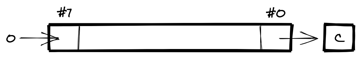
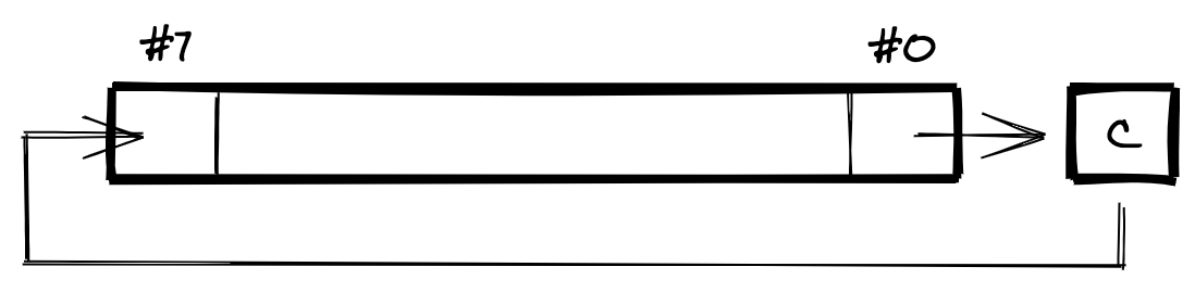
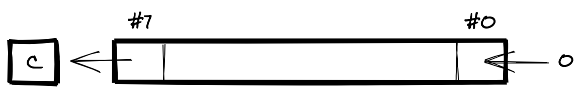
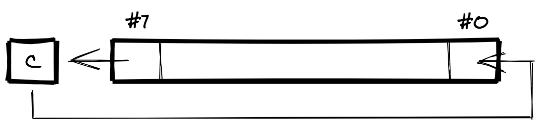
For both types, the bits of the specified byte are shift by one bit to the left or right. The bit that is shifted out of the byte is stored in the Carry flag. (The Carry flag is used as a ninth bit for the operation.) The different between the two types of bit shift is the handling of the bit that is shifted in. For the shift type, the shifted-in bit is always a zero. For the rotate type, the shifted-in bit is set to the old value of the Carry flag.
The following diagram visualises the effect of LSR, the shift right operation:
The following diagram visualises the effect of ROR, the rotate right operation. It shows how the shifted-in bit is treated differently compared to LSR:
The following diagram visualises the effect of ASL, the shift left operation:
The following diagram visualises the effect of ROL, the rotate left operation. It shows how the shifted-in bit is treated differently compared to ASL:
LSR (Shift One Bit Right (Memory or Accumulator))
Shifts the bits of the specified byte one bit to the right, i.e., bit #7 becomes bit #6, bit #6 becomes bit #5, and so on. The new value of bit #7 is zero. The old value of bit #0 is stored in the Carry flag.
Processor Status register changes
| Flag | Effect |
|---|---|
| Zero flag | Set if the shifted byte is zero, otherwise cleared. |
| Negative flag | Always cleared (because bit #7 becomes zero). |
| Carry flag | The old value of bit #0 is stored here. |
Supported addressing modes
| Addressing mode | Example instruction |
|---|---|
| Accumulator | LSR A |
| Absolute | LSR $0000 |
| Zero Page | LSR $00 |
| Absolute, X | LSR $0000, X |
| Zero Page, X | LSR $00, X |
ASL (Shift Left One Bit (Memory or Accumulator))
Shifts the bits of the specified byte one bit to the left, i.e., bit #0 becomes bit #1, bit #1 becomes bit #2, etc. The new value of bit #0 is zero. The old value of bit #7 is stored in the Carry flag.
Processor Status register changes
| Flag | Effect |
|---|---|
| Zero flag | Set if the shifted byte is zero, otherwise cleared. |
| Negative flag | Set to the value of bit #7 in the shifted byte. |
| Carry flag | The old value of bit #7 is stored here. |
Supported addressing modes
| Addressing mode | Example instruction |
|---|---|
| Accumulator | ASL A |
| Absolute | ASL $0000 |
| Zero Page | ASL $00 |
| Absolute, X | ASL $0000, X |
| Zero Page, X | ASL $00, X |
ROL (Rotate One Bit Left (Memory or Accumulator))
Rotates the bits of the specified byte by one bit to the left, i.e., bit #0 becomes bit #1, bit #1 becomes bit #2, etc. The new value of bit #0 comes from the Carry flag, and then the old value of bit #7 is used to update the Carry flag.
Processor Status register changes
| Flag | Effect |
|---|---|
| Zero flag | Set if the rotated byte is zero, otherwise cleared. |
| Negative flag | Set to the value of the new bit #7 (which was bit #6 in the original byte). |
| Carry flag | The old value of bit #7 is stored here. |
Supported addressing modes
| Addressing mode | Example instruction |
|---|---|
| Accumulator | ROL A |
| Absolute | ROL $0000 |
| Zero Page | ROL $00 |
| Absolute, X | ROL $0000, X |
| Zero Page, X | ROL $00, X |
ROR (Rotate One Bit Right (Memory or Accumulator))
Rotates the bits of the specified byte by one bit to the right, i.e., bit #7 becomes bit #6, bit #6 becomes bit #5, and so on. The new value of bit #7 comes from the Carry flag, and then the old value of bit #0 is used to update the Carry flag.
Processor Status register changes
| Flag | Effect |
|---|---|
| Zero flag | Set if the rotated byte is zero, otherwise cleared. |
| Negative flag | Set to the previous value of the Carry flag. |
| Carry flag | The old value of bit #0 is stored here. |
Supported addressing modes
| Addressing mode | Example instruction |
|---|---|
| Accumulator | ROR A |
| Absolute | ROR $0000 |
| Zero Page | ROR $00 |
| Absolute, X | ROR $0000, X |
| Zero Page, X | ROR $00, X |
The JMP operation
The Program Counter stores the address of the next instruction for the CPU. Normally the CPU is automatically updating the address in this register. It increments the address so that it sequentially executes the program. But in any non-trivial program you will need more control. For example, you might want to conditionally execute a particular instruction. Or you might want to loop over a sequence of instructions a certain number of times. For this, there are operations for adjusting the value of the Program Counter.
A simple means of controlling program execution is the JMP operation. This is like the 'goto' instruction that exists in some programming languages. It is an unconditional update of the Program Counter to the address specified as the operand.
JMP (Jump to New Location)
Sets the Program Counter to the memory location specified by the operand.
Processor Status register changes
Does not update any flags.
Supported addressing modes
| Addressing mode | Example instruction |
|---|---|
| Absolute | JMP $0000 |
| Absolute Indirect | JMP ($0000) |
Note that normally you would use a label as the operand, rather than a literal address.
You can use a JMP instruction to create an infinite loop:
loop:
  ; Put any instructions here
  ; that you want to repeat forever.
  JMP loop
Branch operations
A JMP instruction results in an unconditional update of the Program Counter. But sometimes you only want to update the Program Counter if some condition is true. You can do this using one of eight branch operations. Each tests the condition of a particular flag in the Processor Status register. The instruction only updates the Program Counter if that flag has a particular state. If the flag is not in the required state, the instruction has no effect. Program execution continues sequentially as normal.
There are eight branch operations. Each branch operation does not update the state of any Processor Status flags. Each only supports the Relative addressing mode.
BMI (Branch on Result Minus)
Only branches if the Negative flag is set.
Processor Status register changes
Does not update any flags.
Supported addressing modes
| Addressing mode | Example instruction |
|---|---|
| Relative | BMI $00 |
BPL (Branch on Result Plus)
Only branches if the Negative flag is not set.
Processor Status register changes
Does not update any flags.
Supported addressing modes
| Addressing mode | Example instruction |
|---|---|
| Relative | BPL $00 |
BVS (Branch on Overflow Set)
Only branches if the Overflow flag is set.
Processor Status register changes
Does not update any flags.
Supported addressing modes
| Addressing mode | Example instruction |
|---|---|
| Relative | BVS $00 |
BVC (Branch on Overflow Clear)
Only branches if the Overflow flag is not set.
Processor Status register changes
Does not update any flags.
Supported addressing modes
| Addressing mode | Example instruction |
|---|---|
| Relative | BVC $00 |
BCS (Branch on Carry Set)
Only branches if the Carry flag is set.
Processor Status register changes
Does not update any flags.
Supported addressing modes
| Addressing mode | Example instruction |
|---|---|
| Relative | BCS $00 |
BCC (Branch on Carry Clear)
Only branches if the Carry flag is not set.
Processor Status register changes
Does not update any flags.
Supported addressing modes
| Addressing mode | Example instruction |
|---|---|
| Relative | BCC $00 |
BEQ (Branch on Result Zero)
Only branches if the Zero flag is set.
Processor Status register changes
Does not update any flags.
Supported addressing modes
| Addressing mode | Example instruction |
|---|---|
| Relative | BEQ $00 |
BNE (Branch on Result Not Zero)
Only branches if the Zero flag is not set.
Processor Status register changes
Does not update any flags.
Supported addressing modes
| Addressing mode | Example instruction |
|---|---|
| Relative | BNE $00 |
The operand for each branch instruction is a single byte. It is a relative shift that the CPU should apply to the Program Counter if the branch condition evaluates to true. The fact that the operand is a single byte means that the resulting shift can only be in the range -128 to +127 inclusive. You cannot branch to anywhere in your program in the way that you can with a JMP instruction.
This restriction is a deliberate optimisation by the 6502's designers. A program will typically include many branch instructions. Using a one-byte shift rather than a two-byte address means that they are one byte smaller. Over an entire program, this results in a useful reduction in program size. If you do make the mistake of trying to branch too far, the assembler should emit an error.
Normally you would use a label as the operand for a branch instruction:
BMI some_label ; some_label is declared elsewhere.
When using a label, the assembler automatically replaces it by a calculated value. This is the relative shift required to jump from the branch to the label declaration.
Branch instructions are often used with the byte comparison and bit test instructions. (These are CMP, CPX, CPY, and BIT.) First you perform a test using one of the comparison instructions. Then you use a branch instruction to branch based on the result of that test. You can use this technique to create for-loops.
Say you want to initialise a sequence of 8 bytes in memory. The address range of the sequence is $0010 to $0017 and you want to set all the bytes to the value $FF. The following assembly implements this using a for-loop in the form for (i = 0; i < 8; i++):
  LDA #$FF ; Load the Accumulator with the value to set all bytes to.
  LDX #$00 ; Load the X register with the initial value for the loop counter.
loop:
  ; The loop body
  STA $10, X ; Set the value of the byte at $0010 + X to $FF.
  ;
  INX      ; Increment the loop counter in the X register
  CPX #$08 ; Compare the limit value ($08) with the value in the X register.
           ; If the X register contains the value $08 then the Zero flag gets set.
  BNE loop ; Loop if the Zero flag is not set.
  ; Execution continues here if the branch is not taken.
The branch condition initially evaluates as true and so the CPU takes the branch. Eventually the value in the X register is equal to the limit value. In the above code that limit value is $08. The branch is now not taken and the loop exits.
A more efficient approach is to count down rather than up:
  LDA #$FF ; Load the Accumulator with the value to set all bytes to.
  LDX #$07 ; Load the X register with the limit value minus one.
loop:
  ; The loop body
  STA $10, X ; Set the value of the byte at $0010 + X to $FF.
  ;
  DEX      ; Decrement the value of X register,
           ; which sets the Negative flag if X is now less than zero.
  BPL loop ; Loop if the Negative flag is not set.
  ; Execution continues here if the branch is not taken.
By counting down, you do not need a comparison instruction. This is because the DEX instruction does not only decrement the value in the X register. It also sets the Negative flag if the value in the X register is now less than zero. Now you can use the BPL instruction to branch based on that Negative flag. This is without having to first perform a comparison.
Counting down in this way forces you to treat the counter as a signed byte. This means that the maximum possible starting value for the counter is +127 rather than 255. An alternative is to initialise the X register to the limit value and use BEQ for the branch instruction. This permits a maximum starting value of 255. But the downside that the counter is no longer zero-based.
If you do need to index more than 256 bytes, you can use one of the two techniques described on pages 94 and 95 of the MOS MCS6500 programming manual.
If you need to branch to a location that is too far away, you can combine a JMP instruction with a contrary (a.k.a. complementary) branch instruction. You use the JMP instruction to reach the desired location. You use the branch instruction to conditionally skip over that JMP instruction:
  LDA #$00               ; Load the Accumulator with the value to test
  BEQ no_jump            ; Skip the jump if the Accumulator value is zero
  JMP some_distant_label ; Jump if that value is not zero.
no_jump:
  ; Code here that executes if there was no jump.
A common selection mechanism in a high level language is the switch statement. You can create it by combining the byte comparison and branch instructions. The following is a pseudo-code switch statement. It tests the value in the Accumulator against a series of constants to decide how to proceed:
switch (a) {
  case 0:
    ...
  case 1:
    ...
  case 2:
    ...
  default:
    ...
}
You can create it in assembly like so:
  LDA #$01      ; Load the value to test into the Accumulator.
  CMP #$00      ; Compare case 0 to the Accumulator.
  BEQ a_is_zero ; Branch to the a_is_zero label if the Accumulator contains 0.
  CMP #$01      ; Compare case 1 to the Accumulator.
  BEQ a_is_one  ; Branch to the a_is_one label if the Accumulator contains 1.
  CMP #$02      ; Compare case 2 to the Accumulator.
  BEQ a_is_two  ; Branch to the a_is_two label if the Accumulator contains 2.
  ; Default behaviour here.
Operations for subroutines and call stack management
The JMP and branch instructions are very useful for controlling program execution. But there is a common programming construct that they do not support: the subroutine. A subroutine is a sequence of instructions for performing some task. It is useful when we want to invoke that sequence at various points during program execution. It is usually identified with a label. We could use a JMP instruction to start executing it, but what should happen at the subroutine's end? We cannot JMP back because we could have invoked the subroutine from many possible locations in the program code. We would not know which particular location to return to. And what should happen when that subroutine itself invokes a subroutine?
We need to be able to remember the value of the Program Counter when we enter a subroutine. Doing so would allow use to restore that value to the Program Counter on exit. We also need to be able to do this in a nested fashion, to support calling subroutines from subroutines.
The solution to this problem is a data structure called the call stack. Being a stack it supports pushing values onto it and then popping them off. The CPU implements the call stack as a top-down stack. This means that it grows downwards in memory rather than upwards. One page of system RAM, from addresses $0100 to $01FF, is assigned to it. (This is the page right after the zero page.)
The Stack Pointer keeps track of the top of the stack. This register is only one byte in size. This is okay because only a single page is used for the stack; the MSB of any stack address will always be $01. When a byte is pushed onto the stack, the Stack Pointer is decremented by one. When a byte is popped from the stack, the Stack Pointer is incremented by one.
We must initialise the value of the Stack Pointer at program start. We do this using the TXS operation from earlier in this post. Because the stack is a top-down stack, we have to initialise the Stack Pointer to the value $FF. This is the LSB of the address of the stack page's last byte.
; Initialising the call stack:
LDX #$FF
TXS
To invoke a subroutine, we use the the JSR operation. The operand is the address of the subroutine. You would normally specify this using the subroutine's label. When a JSR instruction is executed, the CPU performs the following actions:
- It pushes the current value of the Program Counter onto the Stack. This is an address so it is two bytes of data.
- It decrements the Stack Pointer by two bytes.
- It updates the Program Counter to the address of the specified subroutine.
Use the RTS operation to exit a subroutine. When it reaches the RTS instruction, the CPU will perform the following actions:
- It fetches the current value of the Stack Pointer.
- It reads the values of the two bytes above that location in the stack.
- It interprets these two bytes as an address in memory and it uses them to update the Program Counter's value.
- It increments the Stack Point by two bytes, so 'removing' that stored address from the stack.
JSR (Jump to Subroutine Saving Return Address)
Jumps to a new location in the program code. Also pushes the current value of the Program Counter onto the stack (two bytes).
Processor Status register changes
Does not update any flags.
Supported addressing modes
| Addressing mode | Example instruction |
|---|---|
| Absolute | JSR $0000 |
RTS (Return from Subroutine)
Pops the top two bytes off of the stack and uses them to update the value of the Program Counter.
Processor Status register changes
Does not update any flags.
Supported addressing modes
| Addressing mode | Example instruction |
|---|---|
| Implied | RTS |
Since only one page of memory is allocated to the stack, there is a limit to how deeply you can nest subroutine calls. (The result of exceeding this limit is termed stack overflow.) It is unlikely that you will ever reach this limit. It is more likely that you will not need to devote the entire stack page to the stack. In that case you are free to treat the unused space as regular system RAM. Since the stack grows downwards from $01FF, it is the initial bytes of the stack page that would be unused.
The MOS MCS6500 programming manual includes the following guidance about subroutines:
[T]he use of subroutines should be limited to those cases where the user expects to duplicate code of significant length several times in the program. In these cases, and only in these cases, is subroutine call warranted rather than the normal mode of knowing the addresses and specifying them in an instruction. In all cases where timing [is] of significant interest, subroutines should also be avoided. Subroutines add significantly to the setup and execution time of problem solution.
When entering a subroutine, you might need to store more than the value of the Program Counter. You might have a particular value in the Accumulator before you call the subroutine. The subroutine might load a different value into the Accumulator. When the subroutine returns, you would not be able to pick up from where you were before.
To deal with this, you can push the value of the Accumulator and the Processor Status register on to the stack. You can also pop them off. This allows you to save extra information onto the stack. You have to manage pushing and popping this data yourself. Perform pushing right at the start of the subroutine, and popping before returning.
PHA (Push Accumulator on Stack)
Pushes the current value of the Accumulator onto the stack.
Processor Status register changes
Does not update any flags.
Supported addressing modes
| Addressing mode | Example instruction |
|---|---|
| Implied | PHA |
PHP (Push Processor Status register on Stack)
Pushes the current value of the Processor Status register onto the stack.
Processor Status register changes
Does not update any flags.
Supported addressing modes
| Addressing mode | Example instruction |
|---|---|
| Implied | PHP |
PLA (Pull Accumulator from Stack)
Pops the topmost byte from the stack and stores it in the Accumulator.
Processor Status register changes
| Flag | Effect |
|---|---|
| Zero flag | Set if the copied value is zero, otherwise cleared. |
| Negative flag | Updated to the value of bit #7 of the copied value. |
Supported addressing modes
| Addressing mode | Example instruction |
|---|---|
| Implied | PLA |
PLP (Pull Processor Status register from Stack)
Pops the topmost byte from the stack and stores it in the Processor Status register.
Processor Status register changes
Updates all flags since the entire value for this register is popped from the stack.
Supported addressing modes
| Addressing mode | Example instruction |
|---|---|
| Implied | PLP |
The following assembly demonstrates storing and restoring the value of the Accumulator:
  LDA #$44 ; Store some value in the Accumulator.
  JSR some_subroutine ; Invoke the subroutine.

some_subroutine:
  PHA ; Push the existing value in the Accumulator to the stack.

  ; Perform the subroutine instructions.
  ; Here I just change the value in the Accumulator.
  LDA #$11 ; Store a different value in the Accumulator.

  PLA ; Restore the old value of the Accumulator.
  RTS ; Return from the subroutine.
Operations for interrupt handling
Sometimes a system event will occur that requires your program's immediate attention. For example, the player might have pressed the Reset button on the NES, or the PPU might have started vblank. We term such an event an interrupt.
The 6502 supports three types of interrupt event:
- The Reset event.
- The interrupt request / break (IRQ/BRK) event.
- The non-maskable interrupt (NMI) event.
You have to include a handler in your program code for each of these three event types. Each handler is a subroutine invoked by the CPU when the corresponding event type occurs. You use an interrupt vector table to map each of the three event types to its handler. Each entry in the table is the address of the handler. The very last six bytes of the CPU's address space, $FFFA to $FFFF, is reserved for this table. Every program that you write must include it and it must be found at that particular range of addresses. Note that the table is not executable code — it is only a sequence of three two-byte addresses.
The three addresses, or vectors, in the table are organised as follows:
| Addresses | Vector |
|---|---|
$FFFA and $FFFB |
NMI |
$FFFC and $FFFD |
Reset |
$FFFE and $FFFF |
IRQ/BRK |
As is standard for the 6502, these addresses are stored in little-endian format. The following is an example of creating the interrupt vector table in assembly:
.segment "INTERRUPT_VECTORS"
.addr nmi_handler
.addr reset_handler
.addr irq_brk_handler
The assembler control command syntax to used to embed the addresses of the handlers. The .segment control command positions the vector table at the correct address. I will explain how this works in a future post.
The Reset event
The Reset event is special. It only occurs when the player powers the NES on or when they press the Reset button while the NES is running. When it is signalled, the CPU performs the following initialisation sequence:
- The Interrupt Disable flag is set.
- The Program Counter is set to the value of the Reset vector.
Your program now begins execution.
The value of the Reset vector is the address of the first instruction for the CPU to execute on program start. This will be the start of your program's initialisation code. Then your program will likely enter an infinite loop that is your main game loop. Thus the Reset handler never returns.
The NMI and IRQ/BRK events
The NMI and IRQ/BRK events occur many times during program execution. The handlers for these two events need to deal with exiting the handler as well as entering it. These events will also interrupt the regular execution of your program. You may need to save particular program state on entering a handler and then restore it on exit.
This is the effective sequence of actions that occur when an interrupt is signalled:
- The CPU pushes the current value of the Program Counter onto the stack.
- The CPU pushes the current value of the Processor Status register onto the stack.
- The CPU reads the vector for the particular type of interrupt that has occurred (NMI or IRQ/BRK).
- The CPU sets the value of the Program Counter to that vector.
- The CPU sets the Interrupt Disable flag of the Processor Status register. This prevents any other IRQ/BRK interrupts from occurring.
Now program execution continues within the handler. When you wish to exit the handler, you must do so using an RTI instruction.
RTI (Return from Interrupt)
Pops the topmost byte from the stack and uses it to update the Processor Status register, then pops the next two bytes from the stack and uses them to update the Program Counter.
Processor Status register changes
Updates all flags since the entire value for this register is updated.
Effectively clears the Interrupt Disable flag if the updated value does not have this flag set.
Supported addressing modes
| Addressing mode | Example instruction |
|---|---|
| Implied | RTI |
This is effective sequence of event that occurs when a handler is exited via an RTI instruction:
- The CPU pops the old value of the Processor Status register from the stack.
- The CPU updates the value of the Processor Status register to that old value. If the old value did not have the Interrupt Disable flag set then this re-enables maskable interrupts.
- The CPU pops the old value of the Program Counter from the stack.
- The CPU updates the value of the Program Counter to that old value.
The CPU only pushes the values of the Processor Status register and Program Counter onto the stack. Your interrupt handler code will likely alter the values of other registers. If you wish to save them then you need to push them to the stack immediately on entering the handler and pop them before exiting.
The difference between the NMI and IRQ/BRK interrupt is that the latter is maskable while the former is not. A maskable interrupt is one that you can silence, meaning that the CPU will ignore whenever it occurs. This will happen as long as the Interrupt Disable flag of the Processor Status register is set. As I covered earlier in this post, you can use the SEI and CLI operations to set and clear the Interrupt Disable flag.
But some interrupts are very important and they have to be handled as quickly as possible. For these cases, the 6502 includes the NMI (non-maskable interrupt). It is not affected by the Interrupt Disable flag. The NES has a single NMI: for the interrupt event that occurs when the PPU starts vblank. This event occurs 60 times a second and indicates when the PPU is idle and so when you can update its state.
The 6502 includes a BRK operation that you can use to signal the IRQ/BRK interrupt event. This causes the IRQ/BRK event handler to be executed.
BRK (Force Break)
Saves the current values of the Processor Status register and Program Counter to the call stack. Transfers control to the IRQ/BRK vector. The break occurs even if the Interrupt Disable flag in the Processor Status register is set (i.e., interrupts are masked).
Processor Status register changes
Sets the Interrupt Disable flag.
Supported addressing modes
| Addressing mode | Example instruction |
|---|---|
| Implied | BRK |
The BRK instruction is useful for debugging. You can insert the instruction in your program where you would like to examine the state of the system. It causes the IRQ / BRK event handler to be invoked, at which point you can perform some debug actions. But this handler gets invoked both when a maskable interrupt event occurs and when you use a BRK instruction. You need to be able to detect the latter case in your handler. When an interrupt occurs the CPU pushes the Processor Status register value to the stack. If the interrupt is because of a BRK instruction, that value is first updated so that the Break flag is set. This allows you, in your IRQ / BRK event handler, to check if the interrupt is actually a break interrupt:
PLA      ; Pop the top byte from stack into the Accumulator.
PHA      ; Push it back onto the stack.
AND #$10 ; Bit-test the Break Flag
BNE your_break_routine ; Branch to your break interrupt handling.
; Normal interrupt handling here.
The no-op operation
The final operation to cover is NOP, the no-op operation. An instruction that does nothing seems to be pointless, but it does have its uses:
A NOP is most commonly used for timing purposes, to force memory alignment, to prevent hazards, to occupy a branch delay slot, to render void an existing instruction such as a jump, or as a place-holder to be replaced by active instructions later on in program development (or to replace removed instructions when reorganising would be problematic or time-consuming).
NOP (No Operation)
Does nothing. It is one byte in size and takes two clock cycles to execute.
Processor Status register changes
Does not update any flags.
Supported addressing modes
| Addressing mode | Example instruction |
|---|---|
| Implied | NOP |
The unofficial opcodes
As stated in this post, there are 151 official opcodes. Since an opcode is one byte in length and one byte can define 256 values, there are other possible opcode values. What would happen if a machine instruction were to have an opcode value that is not one of the 151 official values?
The result would depend on the exact unofficial value used. For some values, the result is a no-op or the NES will freeze until you press the Reset button. For others there are useful effects and a few NES games have made use of them. You can read a good description here of why the unofficial opcodes have the effects they do. This page on the Nesdev wiki looks at which unofficial opcodes are actually useable.
Conclusion
If you have not done any low-level programming before then writing games for the NES involves learning many new concepts. The information presented here should provide a solid base for your NES adventure.
Further reading
Changelog
- 2020-06-23 Draft version
- 2020-08-02 A substantial rework of the explanations for addition and subtraction.
- 2020-08-26 Plain English improvements
- 2021-10-21 Fixed a link
- 2024-04-10 Fixed bugs in STX and STY descriptions
# Comments
Comments on this site are implemented using GitHub Issues. To add your comment, please add it to this GitHub Issue. It will then appear below.